![[GMOS logo]](gmoslogo.gif)
| You are in: Instruments > GMOS > Performance and Use > GMOS Components > MOS > Design instructions > Using an object catalog |
|
Using an object catalog |
Using dedicated GMOS images (pre-imaging) for designing MOS masks has the advantages of being independent of the accuracy of any astrometric calibration and immune against proper motions of alignment stars or objects. However it also requires more telescope time, and requires time between the start of the semester and the start of the MOS observations for the pre-imaging to be taken and the mask to be designed. If targets and alignment stars can be selected from the same object catalogue which has accurate enough relative astrometry, the MOS masks can be created without GMOS pre-imaging. The steps to create an Object Table using an object catalog are:
The Object Table and the pseudo-GMOS image are then used as inputs to GMMPS and from that point on the process of mask creation is the same whether an object catalog or pre-imaging was used.
PIs designing masks from object catalogs should read the recommendations to ensure a good mask design.
The transformations between RA and Dec and GMOS x,y were found by observing astrometric fields containing several tens of stars. The errors on the astrometry of stars used to derive the transformations are ≈30 mas (South) and ≈60 mas (North).
The transformations for GMOS-S and GMOS-N were tested on sky by observing astrometric fields, and noting the displacement between the slit centers and the observed star position. The slits in the test masks were 2"x2" squares to allow the slit centers and the star centroids to be accurately measured. The astrometric fields were taken from the UCAC2 catalog and only stars with position errors of <20 mas were accepted for the design of test masks.
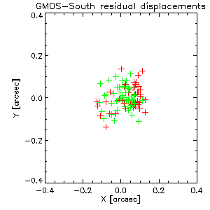
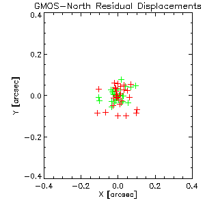
The two plots below show the measured displacements, where green and red symbols indicate results from two different masks rotated by 90 degrees. The maximum displacements are less than 0.15" in North and South and the r.m.s. of the displacements are 0.06" which is less than a single unbinned GMOS pixel.
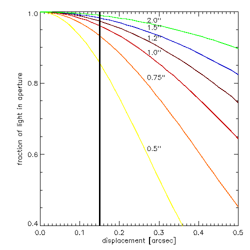
The displacement of an object within a slit translates into loss of flux, with the fraction lost depending on the selected slit width and seeing. The plot below illustrates a simple case of a point source (Gaussian profile) observed through slits with the width matched to the seeing (i.e. 0.5" slit used in 0.5" seeing FWHM) with an extraction aperture of 1.4*FWHM. The color curves indicate the fraction of flux in the aperture as compared to a perfectly centered target for different slit widths. The solid vertical line indicates the maximum displacement measured for the test masks, which can be considered as a conservative estimate of slit losses as most objects on a mask would be displaced by a smaller amount.
The losses should be viewed in terms of the telescope time saving achieved by abandoning the pre-imaging. The plot below indicates the integration time for which the time needed to cover the additional slit losses is still less than the time needed for pre-imaging. It assumes the very minimum time needed for pre-imaging (currently 15 min).

For example, in the above plot, for a slit 1 arcsec wide the break-even exposure time is ~6.5 hours. For all exposure times less than this, adding 15 mins to the exposure time would compensate for the expected slit losses.
The above plots can be used to estimate whether an object catalog is suitable to construct the mask. If the relative accuracy of the astrometric solution for the catalog is similar to the accuracies quoted for the tests, then the displacements can also be expected to be similar. The object catalog must include both your science targets and the alignment stars, with homogeneous astrometry from single solution. In most cases the astrometric accuracy should be better than 0.1" rms. However, for shorter exposures poorer astrometry could still produce an overall time gain. Another point worth consideration is the logistical advantage of being able to design the masks even before the target becomes observable.
The Object Table and pseudo-GMOS image are created using the IRAF task gmskcreate that is (soon to be available) in the Gemini IRAF mostools package. Because this task was not available at the time of the last Gemini IRAF package release (v 1.9.1), it is availble from the following link: http://www.gemini.edu/sciops/data/software/gemini-gmsk.tar.gz. There is a README-GMSK file available.
gmskcreate requires an input file containing information about the spectroscopy candidates, the Gemini program ID and the RA, Dec and position angle of the required Gemini field. Note that this RA, Dec and position angle must be identical to that defined in the Phase-II observations, and the PI must check before submitting the mask that there is a suitable guide star available.
gmskcreate can create an Object Table and/or a pseudo-GMOS image. The pseudo-GMOS image is required for the mask checking but does not have to be of high quality. It is used to verify certain properties of the mask (eg. to make sure the acquisition objects do not fall in the gaps between the CCDs) or to check for gross slit placement problems. It is expected that in most cases the mask will designed using the previously determined astrometry and not by measuring the target pixel positions in the pseudo-GMOS image.
Input data file
The input data file must contain one line per object. Each line must contain values for 'ID', 'RA', 'DEC', 'MAG' in that order and separated by spaces, where 'ID' is an integer ID number for the object, 'RA' and 'DEC' are the Right Ascension and Declination of the object, and 'MAG' is the magnitude of the object.
The line can also optionally contain values for 'priority', 'slitsize_x', 'slitsize_y', 'slittilt' and 'slitpos_y', again in that order and separated by spaces. These values are used by (and can be altered in) GMMPS. 'Priority' is an integer priority (0-3) for the object (0 is for acquisition objects, 1-3 for targets, 1 is highest), 'slitsize_x' is the slit width (real) in arcsecs, 'slitsize_y' is the slit length (real) in arcsecs, 'slittilt' is the position angle of the slit in degrees measured counter-clockwise relative to the default position, and 'slitpos_y' is the slit position in the y-direction relative to the object position (real). It is possible to set the optional values for just a few of the objects in the file, and not all of the optional values must be set. If for any object only a few (or none) of the optional values are set the remaining ones will inherit the default values of priority=1, slittilt=0, slitpos_y=0, and slitsize_x and slitsize_y as given in the input parameters slitszx and slitszy. Note that acquisition objects (priority = 0) must have slitsize_x = 2.0, slitsize_y = 2.0, slittilt = 0 and slitpos_y = 0 so any optional values given for acquisition objects will be ignored.
Please note the following limitations in gmskcreate:
Creating the Object Table
gmskcreate will create the Object Table if fl_getxy=yes.
The Object Table is a FITS table that will contain the following columns:
| ID | Unique object id (integer) |
| RA | RA in hours (real) |
| DEC | Dec in degrees (real) |
| x_ccd | X coordinate of object position in pixels (real) |
| y_ccd | Y coordinate of object position in pixels (real) |
| MAG | (Relative) magnitude of object (real) |
| Priority | Priority of object |
| slitsize_x | Slit width in arcsec (real) |
| slitsize_y | Slit length in arcsec (real) |
| slittilt | Slit position angle in degrees (real) |
| slitpos_y | Slit position in the Y-direction (spatial) relative to the object position in arcsec (real) |
The GMOS x,y pixel values are calculated from the input RA and Dec using the known transformations. It is crucial that the RA and Dec for all objects on the mask (spectroscopy candidates and alignment stars) comes from the same astrometric solution.
The Object Table name is given in the input parameter outtab.The file outtab will be given the extension '.fits' it this is not already included in the name. If fl_getxy=yes and outtab is undefined then the Object Table name will be the indata file name with the prefix 'GMI' and the suffix '_OT.fits'.
The task will also create the file given in the outcoords parameter which is an ascii file containing the GMOS x,y coordinates, one object per line. This file is not required for GMMPS but may be useful for overplotting the GMOS x,y positions on the pseudo-GMOS image using for example the IRAF task tvmark. If fl_getxy=yes and outcoords is undefined then the output file will be the indata file name with the prefix 'GMI'.
Creating the pseudo-GMOS image
gmskcreate will create the pseudo-GMOS image if fl_getim=yes.
The transformation from input image to pseudo-GMOS image is found by first using the input image WCS header keywords to transform the RA and Dec of an evenly distributed grid of 25 positions throughout a 5.5' x 5.5' field of view into input-image x,y positions, and then calculating the transformation between the input-image x,y positions and the GMOS x,y positions (calculated from the RA and Dec and the known transformations).
The transformation from input x,y -> GMOS x,y is calculated using geomap with a polynomial of order 2:
xgmos = a + b*xinp + c*yinp ; ygmos = d + e*xinp + f*yinp
being used for the default fit (allowing for shift, scale and rotation).
This procedure requires that the input image contains the WCS keywords, CRPIX1, CRPIX2, CRVAL1, CRVAL2, CD1_1, CD1_2, CD2_1 and CD2_2. For DSS images these keywords can be added with the iraf command makewcs. The above procedure assumes that the WCS in the input image corresponds reasonably well with the astrometry of the input objects. If this is not the case the user may want to update the WCS of the input image.
If the WCS of the input image and the astrometry of the input objects do not correspond well, this will cause the slits plotted by GMMPS to not lie on top of the objects. This is not a problem for the mask creation, as the GMOS x,y positions are taken from the Object Table and not from the image, but it may make it more difficult to check the mask.
The pseudo-GMOS image is given the name in the outimage parameter with the prefix 'GMI' added. The prefix is necessary to identify images as pseudo-GMOS images when they are submitted to the observatory using the Observing Tool. If outimage is undefined then the output image name will be created from the inimage name with the prefix GMI.
Input files are:
File containing object information - testSinfo
DSS image to create the pseudo GMOS image - testSdss.fits
Input file testSinfo contains:
| 10 | 201.677257883333 | -47.6515697833333 | 17 | 2 | 1.0 | 15.0 | 0 | -3.5 |
| 11 | 201.688305283333 | -47.6419452833333 | 17 | |||||
| 12 | 201.667492283333 | -47.6539157833333 | 17 | 2 | 1.0 | 15.0 | 0 | 3.5 |
| 13 | 201.684278788889 | -47.6611405944444 | 17 | |||||
| 14 | 201.711239283333 | -47.6472018833333 | 17 | 3 | ||||
| 15 | 201.693645883333 | -47.6295318055556 | 17 | |||||
| 16 | 201.699520483333 | -47.6311801833333 | 17 | |||||
| 17 | 201.696407683333 | -47.6678355833333 | 14.6 | 0 | ||||
| 18 | 201.712337883333 | -47.6368487833333 | 14.3 | 3 | 1.0 | 20.0 | -25 | |
| 20 | 201.644170833333 | -47.6834166666667 | 14.7 | 0 | ||||
| 21 | 201.735362499844 | -47.6117805555556 | 14.6 | 0 |
In this case the user has set the priority, slitsize_x, slitsize_y, slittilt and slitpos_y for the first and third objects in the file (id = 10 and 12). The priority has also been changed from the default value priority = 1 to priority = 3 for object id = 14. The priority, slitsize_y and slittilt has been changed for object id = 18. Note that if you do not want to specify all of the optional values you still must specify all the values preceeding the last one whose value you wish to change for an individual object id. Objects id = 17, 20 and 21 are examples of acquisition objects where priority is set to 0, the slitsize_x, slitsize_y, slittilt and slitpos_y values will automatically default to values of 2.0, 2.0, 0 and 0 even if the user had specified other values for the optional parameters. The aquisition objects can be selected interactively in GMMPS, however, it is important for the object table to contain enough appropriate sources. Having additional acquisition objects to choose from will allow more flexibility during the design in GMMPS.
To create the object table and pseudo-GMOS image use the command:
gmskcreate indata=testSinfo gprgid=GS-2007A-Q-01 instrument=gmos-s rafield=201.68298 decfield=-47.64762 pa=0 fl_getxy=yes fl_getim=yes inimage=testSdss.fits iraunits=degrees fraunits=degrees
Output files are:
File containing GMOS x,y - GMItestSinfo
Object Table - GMItestSinfo_OT.fits
pseudo-GMOS image - GMItestSdss.fits
log file - gmos.log
The Object Table contains:
| # row | ID | RA | DEC | x_ccd | y_ccd | MAG | priority | slitsize_x | slitsize_y | slittilt | slitpos_y |
|---|---|---|---|---|---|---|---|---|---|---|---|
| # | H | deg | pixels | pixels | mag | arcsec | arcsec | degrees | arcsec | ||
| 1 | 10 | 13.44515 | -47.65157 | 3291.15 | 2561.971 | 17. | 2 | 1. | 15. | 0. | -3.5 |
| 2 | 11 | 13.44589 | -47.64194 | 2924.589 | 2088.102 | 17. | 1 | 1. | 5. | 0. | 0. |
| 3 | 12 | 13.4445 | -47.65392 | 3615.198 | 2677.604 | 17. | 2 | 1. | 15. | 0. | 3.5 |
| 4 | 13 | 13.44562 | -47.66114 | 3058.212 | 3033.215 | 17. | 1 | 1. | 5. | 0. | 0. |
| 5 | 14 | 13.44742 | -47.6472 | 2163.629 | 2347.128 | 17. | 3 | 1. | 5. | 0. | 0. |
| 6 | 15 | 13.44624 | -47.62953 | 2747.09 | 1476.672 | 17. | 1 | 1. | 5. | 0. | 0. |
| 7 | 16 | 13.44663 | -47.63118 | 2552.111 | 1557.89 | 17. | 1 | 1 | 5. | 0. | 0. |
| 8 | 17 | 13.44643 | -47.66784 | 2655.82 | 3363.201 | 14.6 | 0 | 2. | 2. | 0. | 0. |
| 9 | 18 | 13.44749 | -47.63685 | 2126.774 | 1837.188 | 14.3 | 3 | 1. | 20. | -25. | 0. |
| 10 | 20 | 13.44294 | -47.68342 | 4390.637 | 4133.773 | 14.7 | 0 | 2. | 2. | 0. | 0. |
| 11 | 21 | 13.44902 | -47.61178 | 1358.337 | 599.6895 | 14.6 | 0 | 2. | 2. | 0. | 0. |
Catalogs: There are various astrometric catalogs than can be used to produce accurate relative astrometry for an input object catalog. Here we provide links to some of the commonly used catalogs.
Images: GMMPS requires that certain keywords are in the pseudo-GMOS image header. The gmskcreate script adds these required keywords to the header. GMMPS has been run successfully with images from the following sources. Note that this does not test the astrometric accuracy of the masks, just that the mask software is able to create the masks when the input images come from these sources. Please report any problems with using images from other sources via the Gemini helpdesk under the topic Gemini IRAF.
Tested with images from:
The capability to design MOS masks from object catalogs is a new capability (since late 2007) for Gemini. Because there is a greater potential for failure, PIs must understand that they use this capability at their own risk. We offer the following suggestions to minimize the chances for losing significant amounts of observing time due to a poorly designed mask:
Use the Gemini MOS Mask Preparation Software (GMMPS) to create an Object Definition File (ODF)
![]()
![]()
In Original Form October 25, 2007; Kathy Roth, Ilona Soechting