| You are in: Observing Tool (OT) > Science Program > Elements > OT Components and Iterators > OT NIRI |
 |
Near-IR Imager (NIRI) in the Observing Tool |
This page explains how to configure the near-infrared imager (NIRI) in the Observing Tool:
For examples of typical NIRI Observations, "fetch" the NIRI OT Library from the database using the Observing Tool (the library is located in the "Other" OT programs).
Important note: Phase II files for NIRI and for NIRI+ALTAIR are required to contain acquisition sequences (spectroscopic) and all calibrations (flats, arcs, and standard/calibration stars). Examples of observations (with acquisition sequences and calibrations) as well as separate sections containing flat, arc, and photometric standards are contained in the NIRI OT Library.
Refer to the NIRI instrument pages and, in particular, the NIRI observing strategies page for information on how best to use the instrument.
See the NIRI OT tips & tricks the NIRI checklist, and the NIRI Common Problems for common questions and mistakes that the PI needs to consider.
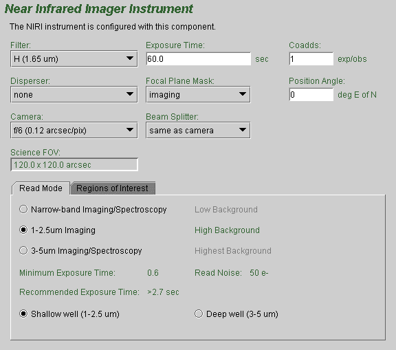
The detailed component editor for NIRI is accessed in the usual manner, by selecting the NIRI component in your science program, and is shown below:

Choice of camera, beam splitter, filter, dispersing element and focal plane mask (slit) is made by clicking on the pull down lists (i.e. the down-pointing arrows) and selecting the desired item. For example, there are three cameras f/32, f/14 and f/6, which are normally used with the "same as camera" beam splitter. Note how the window displaying the science field of view changes automatically to reflect the choice of camera, focal plane mask, and beam splitter. For direct imaging no dispersing element is required. Several grisms are available for spectroscopy. When a grism is selected, be sure to select the proper order-sorting filter as well. The desired focal plane mask (e.g. a slit of specified width) should also be selected. Again, the science field of view will reflect the slit chosen.
If you display a view of the field with the position editor and have selected the "science area" button, then this too will reflect the choices of NIRI camera and focal plane mask.
For imaging observations, the filter is chosen by selecting one from the list (by clicking on it). The central wavelength is given for each filter to assist with identification. You can move the vertical slider bar or click on the arrow buttons to browse the list. Note that the proper order-sorting filter should be selected for grism spectroscopic observations.
The exposure time is set by clicking in the relevant window and typing the required number of seconds. Each occurrence of the observe element will cause N exposures to be taken and coadded in the instrument control system. The value of N is set by typing an integer in the "coadds" window. The total exposure in each output image will be the exposure times the number of coadds.
The facility Cassegrain Rotator can rotate the instrument to any desired angle. The angle (in conventional astronomical notation of degrees east of north) is set by typing in the "position angle" window. The view of the science field in the position editor will reflect the selected angle. Alternatively the angle may be set or adjusted in the position editor itself by interactively rotating the science field.
The NIRI array is read out in different modes for different kinds of observations. Select the button corresponding to the desired mode. Note that the read noise, recommended minimum exposure time, and suggested background regime are indicated in green to the left and below; they change as the different read modes are selected. The array bias voltage can also be set for "deep well" and "shallow well." The choice of bias voltage affects the well depth, but not the minimum integration time or read noise. Note that the array read mode can be changed in the NIRI iterator, but the bias voltage cannot.
A smaller sub-array can be read out more quickly than the whole NIRI array. By clicking on the "Regions of Interest" tab, one sees the options available. Each subarray is centered on the array. Sub-array readout should be used to reduce the minimum integration time (not yet indicated on the "Read Mode" tab).
The save button accepts the latest changes and stores the program to the local database, the undo/redo button (and, transiently, the edit pencil) toggles pending and saved changes and the close button closes the science program editor (saving any changes to the local database).
The NIRI Iterator is a member of a class of instrument iterators. Each works exactly the same way, except that different options are presented depending upon the instrument. Below we see a few of its features:

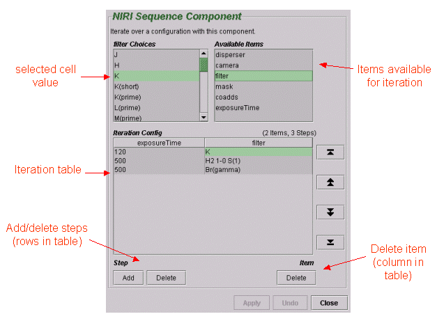
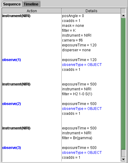
You set up an iteration sequence by building an Iteration Table. The table columns are items over which to iterate. In this example we are iterating over filters and exposure time so there are two corresponding columns in the table. Table rows correspond to iterator steps. At run time, all the values in a row are set at once. Since there are three steps in this table, an observe element nested inside the NIRI iterator would produce an observe command for each of three filters, using the specified integration times:

The items that are available for inclusion in the iterator table are shown in the box in the upper right-hand corner. Selecting one of these items moves it into the table in its own column. Each cell of the table is selectable. The selected cell is highlighted green. When a cell is selected, the available options for its value are displayed in the box in the upper left-hand corner. For example, when a cell in the filter column is selected, the available filters are entered into the text box. When a cell in the integration time column is picked, the upper left-hand corner displays a text box so that the number of seconds can be entered.
Rows or columns may be added and removed at will. Rows (iteration steps) may be rearranged using the arrow buttons.
NOTE: At present the NIRI OIWFS is not available for use.
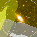
The mechanical layout of NIRI includes a set of 45 degree pick-off (beam splitter) mirrors which feed the (unobscured) science light path and pass the rest of the ~3 arcmin field to the on-instrument wavefront sensor. Each pick-off mirror is sized appropriately for the FOV of the corresponding camera. The obscuration pattern and region accessible to OIWFS guide stars can be viewed with the position editor by using the view...OIWFS display item in the position editor menu bar.
There are two aspects of note to this display. Firstly the obscured region can be viewed in outline or blocked out. The former is useful for determining if there are potential guide stars hidden by the mirror support struts. In cases where the science orientation is not critical, it may be possible to use such stars with the OIWFS by rotating the instrument position angle. Secondly, the mirrors and support struts are not located at a focal plane and so there is progressive vignetting of the beam near their edges. The obscuration pattern may be viewed with and without this partial vignetting. It might be possible to use a guide star in the partially vignetted region if it is bright (although usually it will be preferable to rotate the instrument slightly).
The obscuration pattern changes depending on the beam splitter selected.
Last update February 6, 2006; Andrew Stephens & Tom Geballe
In original form March 26, 1998; Phil Puxley