| You are in: Observing Tool (OT) > Science Program > Elements > OT Components and Iterators > OT GMOS |
 |
Gemini Multi-Object Spectrographs (GMOS)
|
This page explains how to configure the Gemini Multi-Object Spectrographs (GMOS) in the Observing Tool. There are separate components and iterators for GMOS-N and GMOS-S (because the list of filters, gratings etc may differ):
Refer to the GMOS instrument pages and, in particular, the GMOS observing strategies page for information on how best to use the instrument.
See the GMOS OT tips & tricks
for required OT observations and components for programs of different types, as well as other tips
on how to define GMOS observations in the OT.
See the GMOS
checklist for common questions (and mistakes) that the PI needs to consider.
See the GMOS OT library for
example OT observations.
The detailed component editor for GMOS is accessed in the usual manner, by selecting the GMOS component in your science program, and is shown below. Select the GMOS-N component if your program is scheduled for Gemini-North; select GMOS-S if your program is scheduled for Gemini-South. The examples below show GMOS-N but the windows look similar for GMOS-S.
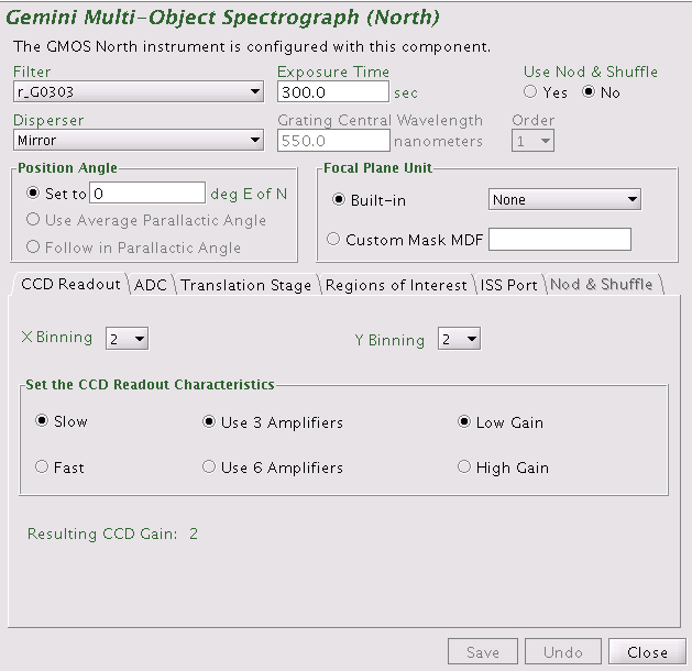
The filter is chosen by clicking on the pull down list (i.e. the down-pointing arrow) and selecting the desired filter. The filter names match those listed on the GMOS-N and the GMOS-S filter pages. In spectroscopic mode, all filters can be used as blocking filters as required by your science program. There is no requirement to use a filter in spectroscopic mode. The filters g_G0301, r_G0303, i_G0302, and z_G0304 can be used for broad-band imaging.
The exposure time is set typing the number of seconds in the "Exposure Time" field.
Choice of grating (for spectroscopy) or mirror (for imaging) is made by clicking on the pull down lists (i.e. the down-pointing arrows) and selecting the desired item. If a grating is chosen, the grating central wavelength must also be set and the order chosen. Currently all gratings are used in first order, only.
Choice of one of the built-in focal plane units is made by clicking on the pull down lists (i.e. the down-pointing arrows) and selecting the desired unit. The built-in focal plane units included various longslits and the IFU. For imaging, the focal plane unit should be set to "None". For MOS observations a custom Mask Definition File (MDF) is needed. Select the custom mask MDF by clicking the "radio"-button. Then type the MDF label supplied from the Gemini Observatory for your observation(s) in the field to the right.
Note that the longslit length for nod-and-shuffle observations is approximately 1/3 of the regular longslit (to provide sufficient un-illuminated areas on the detector within which to shuffle the charge). Make sure that you have selected the correct slit for your observations.
If you display a view of the field with the position editor and have selected the "science area" button, then this will reflect the choice of focal plane unit (displayed as a blue box). Note that because of their small field of view, the two integral field unit 'apertures' can be quite hard to see. Currently, all custom mask MDFs are shown as the largest field of view within which slit-lets can be cut.
The facility Cassegrain Rotator can rotate the instrument to any desired angle. The angle (in conventional astronomical notation of degrees east of north) is set by typing in the "position angle" window. The view of the science field in the position editor will reflect the selected angle. Alternatively the angle may be set or adjusted in the position editor itself by interactively rotating the science field.
Select the binning in the X and Y direction by clicking on the pull down lists (i.e. the down-pointing arrows). No binning (1), and binning by 2 and 4 are supported. For imaging mode, the binning in X and Y should be set identically. For the spectroscopic modes, binning in X is equivalent to binning in the spectral direction, while binning in Y is equivalent to binning in the spatial direction.
Select the desired read-out mode, use of amplifiers and the CCD gain by clicking the "radio"-buttons. The available modes are those listed as suggested settings on the GMOS-North Detectors and the GMOS-South Detectors web pages. It is recommended to use only 3 amplifiers (the best 3), unless the read-out speed has to be minimized to accomplish the science goals of the observation.
The atmospheric dispersion corrector (ADC) for GMOS is not yet available. Thus, the selection defaults to "No Correction".
The GMOS detector is equipped with a translation stage to compensate for flexure. The default setting, "Follow in X and Y", currently gives the best flexure compensation for GMOS-N. For GMOS-S, the default setting is "Follow in X, Y and Z". For daytime calibration such as arcs and mask images taken when the telescope is stationary the translation stage should be set to "Do Not Follow" for GMOS-N and "Follow in Z Only" for GMOS-S.
The GMOS detector can be configure to either read out the full frame or read out a smaller region of interest. The default is to read out the full frame. To change this, click on the "Regions of Interest" tab and then click the "radio"-button on the preferred region of interest.
The GMOS detector array is 6144 pixels by 4608 pixels. The regions read out for the different choices of region of interest are given in the table below as [x1:x2,y1:y2], where x1 and x2 are the starting and ending pixel in the X direction and y1 and y2 are the starting and ending pixel in the Y direction. The regions are given in unbinned pixels. All regions of interest can be used with all binnings; the software takes care of any needed conversions. The table below also lists typical use for the different regions of interest. Currently the chosen region of interest is not visualized in the Position Editor.
| Name of ROI | [x1:x2,y1:y2] | Common use |
| Full Frame Readout | [1:6144,1:4608] | Most science observations. |
| CCD2 | [2049:4096,1:4608] | Longslit with color filters when useful wavelength range can fit on 2048 pixels. |
| Central Spectrum | [1:6144,1792:2815] | The central 1024 rows. Longslit spectra of point sources (standard stars). |
| Central Stamp | [2922:3221,2154:2453] | The central 300pix x 300pix. Imaging of single standard stars. |
| Top Spectrum | [1:6144,3328:4351] | 1024 rows in top part of longslit. Longslit spectra of point sources. |
| Bottom Spectrum | [1:6144,256:1279] | 1024 rows in bottom part of longslit. Longslit spectra of point sources. |
The location of the GMOS OIWFS patrol field on the sky depends on which ISS port on the telescope has GMOS mounted. Normally GMOS is mounted on the "side-looking" ISS port. The OT has this selection as its default. It is important to make sure that the correct ISS port is selected for the current semester, since it affects whether the selected OIWFS guide star can be reached.
First you must select nod-and-shuffle mode using the radio-button in the upper right hand corner of the GMOS component. Once that is selected, the nod-and-shuffle tab becomes active. (Depending on the size of your window, you may have to use the arrows to the right of the tabs to locate it). The content of the nod-and-shuffle tab is shown below.
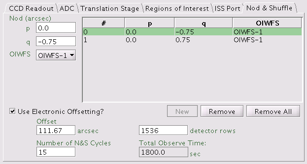
The following items need to be defined by the user:
![]() Note that when
using nod-and-shuffle, an observation cannot also contain an offset iterator.
Note that when
using nod-and-shuffle, an observation cannot also contain an offset iterator.
The save button accepts the latest changes and stores the program to the local database, the undo/redo button (and, transiently, the edit pencil) toggles pending and saved changes and the close button closes the science program editor (saving any changes to the local database).
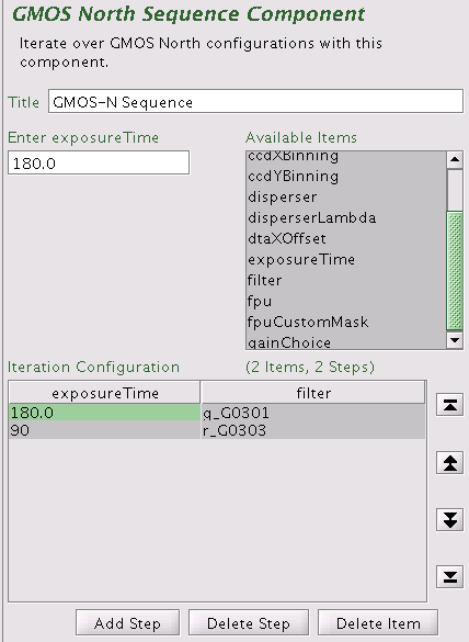
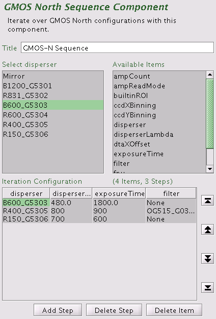
The GMOS Iterator is a member of a class of instrument iterators. Each works exactly the same way, except that different options are presented depending upon the instrument. Below some of its features are shown in two examples. The first example is for imaging, the second example for longslit spectroscopy. The iteration sequence is set up by building an Iteration Table. The table columns are items over which to iterate.
The items that are available for inclusion in the iterator table are shown in the box in the upper right-hand corner of the GMOS Sequence Components figures below. Selecting one of these items moves it into the table in its own column. Each cell of the table is selectable. The selected cell is highlighted green. When a cell is selected, the available options for its value are displayed in the box in the upper left-hand corner. For example, when a cell in the filter column is selected, the available filters are entered into the text box. When a cell in the exposure time column is picked, the upper left-hand corner displays a text box so that the number of seconds can be entered. When a cell in the "disperserLambda" column is picked, the upper left-hand corner displays a text box so that the central wavelength in nanometers can be entered.
![]() Note that when
using nod-and-shuffle, an observation cannot also contain an offset iterator.
Note that when
using nod-and-shuffle, an observation cannot also contain an offset iterator.
Rows or columns may be added and removed at will. Rows (iteration steps) may be rearranged using the arrow buttons.
 |
 |
| GMOS iterator example for imaging | The resulting sequence with one observe element and no offset iterator |
In this example the sequence iterates over filters and exposure times so there are two corresponding columns in the table. Table rows correspond to iterator steps. At run time, all the values in a row are set at once. Since there are two steps in this table, an observe element nested inside the GMOS iterator would produce an observe command for each filter using the specified integration times.
 |
 |
| GMOS iterator example for longslit spectroscopy | The resulting sequence with one observe element and no offset iterator |
In this example the sequence iterates over the central wavelength and over the gratings so there are two corresponding columns in the table. Table rows correspond to iterator steps. At run time, all the values in a row are set at once. Since there are three steps in this table, an observe element nested inside the GMOS iterator would produce an observe command for each of three steps. Iteration of the central wavelength may be useful due to the gaps between the three detectors.
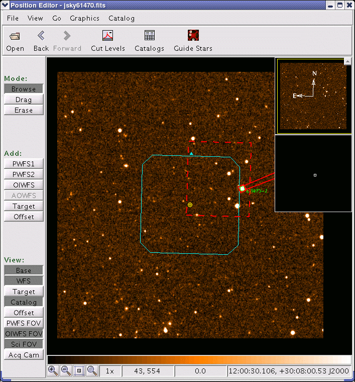
GMOS is equipped with an on-instrument wavefront sensor (OIWFS). The region accessible to the OIWFS is a rectangular field, partly inside the imaging field of view, see the GMOS OIWFS page for details. The OIWFS arm vignettes a small part of the field of view if a guide star inside the imaging field of view is chosen. The vignetting and the region accessible to OIWFS can be viewed with the position editor by using the view...OIWFS FOV item in the position editor menu bar. An example of this is shown in the figure below; the accessible patrol field is outlined with the red dashed line and the projected vignetting of the OIWFS is shown shaded in red). The example is shown for GMOS on the side-looking ISS port.
In cases where the science orientation is not critical, it is possible to rotate the instrument position angle to reach stars at other locations in the field.
Last update: June 16, 2005; Bryan Miller
Pervious version: August 24, 2004; Kathy Roth