![[3D telescope model]](tel-mod.gif)
![[3D telescope model]](tel-mod.gif)
|
Acquisition and Guidance Unit Layout |
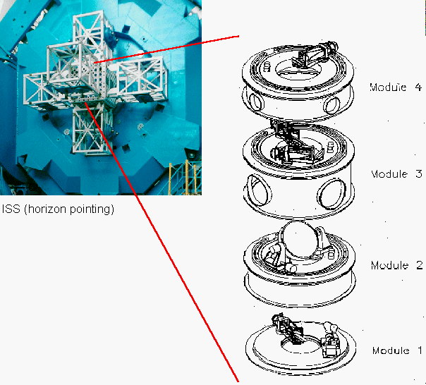
To understand the limitations on use of the peripheral wavefront sensors (PWFSs), acquisition camera, polarisation modulator (when available) and how the telescope beam is redirected to the instruments or from the facility calibration unit, it is useful to visualise the nested modules of the Acquisition and Guidance (A & G) system.
The A & G is located within the instrument support structure (ISS) mounted on the cassegrain rotator which may be rotated to any desired position angle (and normally moves to de-rotate the field of the alt-az telescope).

The A & G module contents are:
Modules 2, 3 and 4 may rotate independently about the vertical axis.
Last update September 22, 1999; Phil Puxley